Instruction for the Tube Tester Type W 19
| Titel | Instruction for the Tube Tester Type W 19 |
|---|---|
| Tags | |
| Hersteller | Funke (Adenau) |
| Breite × Höhe | 104 mm × 199 mm |
| Seitenanzahl | 16 |

Versionen der Bilder dieser Seite:
- Bearbeitet (247,4 kB) – Angezeigte Version
- Unbearbeiteter Scan (13,7 MB)
Text auf dieser Seite
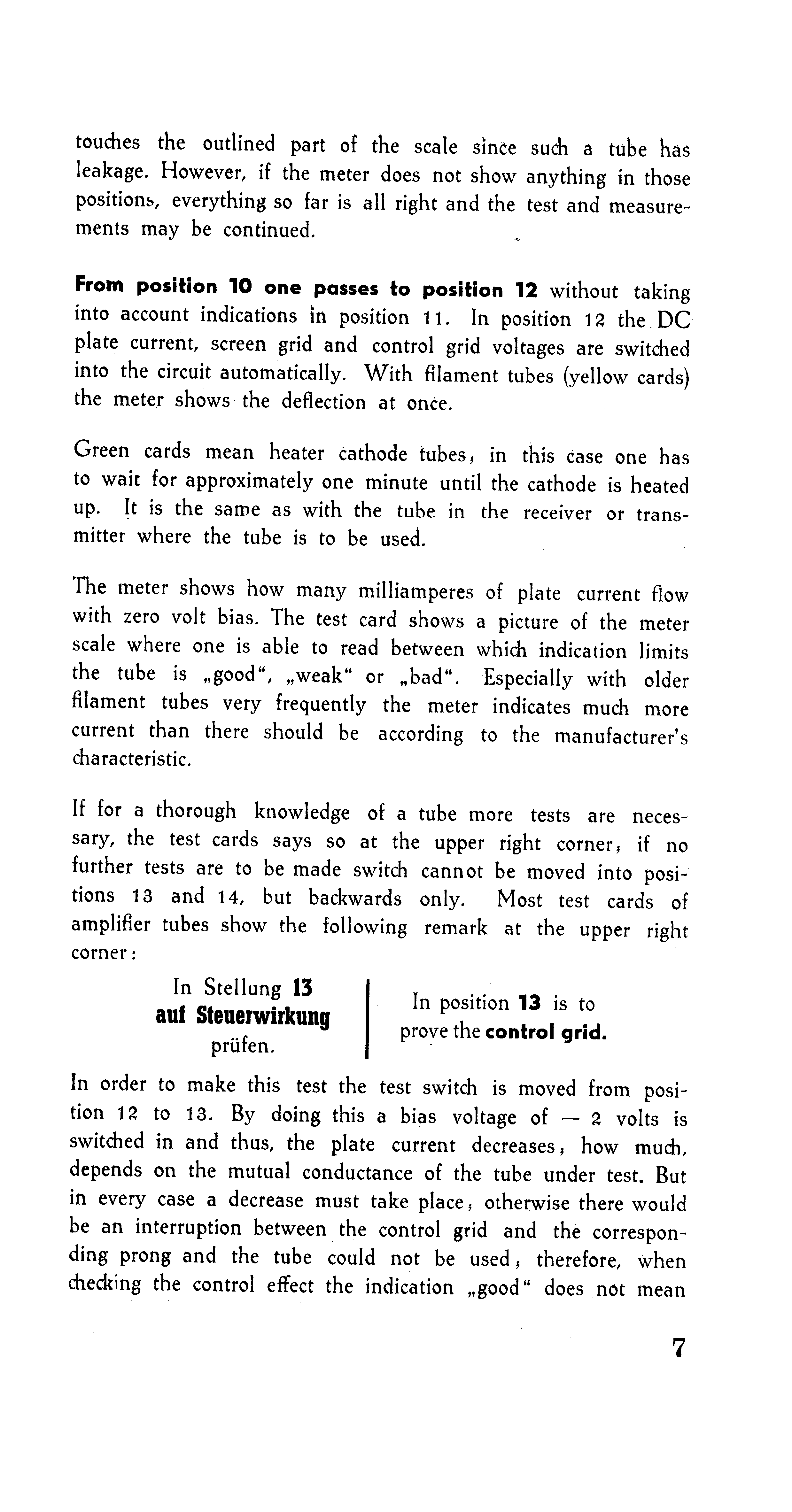
touches the outlined part of the scale since such a tube has leakage. However, if the meter does not show anything in those positions, everything so far is all right and the test and measurements may be continued.
From position 10 one passes to position 12 without taking into account indications in position 11. In position 12 the DC plate current, screen grid and control grid voltages are switched into the circuit automatically. With filament tubes (yellow cards) the meter shows the deflection at once.
Green cards mean heater cathode tubes, in this case one has to wait for approximately one minute until the cathode is heated up. It is the same as with the tube in the receiver or transmitter where the tube is to be used.
The meter shows how many milliamperes of plate current flow with zero volt bias. The test card shows a picture of the meter scale where one is able to read between which indication limits the tube is „good“, „weak“ or „bad“. Especially with older filament tubes very frequently the meter indicates much more current than there should be according to the manufacturer’s characteristic.
If for a thorough knowledge of a tube more tests are necessary, the test cards says so at the upper right corner, if no further tests are to be made switch cannot be moved into positions 13 and 14, but backwards only. Most test cards of amplifier tubes show the following remark at the upper right corner:
In Stellung 13
auf Steuerwirkung
prüfen.
In position 13 is to prove the control grid.
In order to make this test the test switch is moved from position 12 to 18. By doing this a bias voltage of —2 volts is switched in and thus, the plate current decreases; how much, depends on the mutual conductance of the tube under test. But in every case a decrease must take place, otherwise there would be an interruption between the control grid and the corresponding prong and the tube could not be used, therefore, when checking the control effect the indication „good“ does not mean
Weitere Dokumente in diesem Satz „Konvolut Dokumente Funke Adenau“:
- Schaltplan W20
- Prüfkartenindex im Kartenformat
- Hinweiszettel: „Vorsicht! Empfindliche Elektrische Meßgeräte“
- Transistor-Adapter für die Röhrenmeßgeräte W19 + W20
- FUNKE – Personenruf-Funkanlage in freier Strahlung
- FARBFERNSEHBILDRÖHREN-MESSGERÄT für den Kundendienst
- FUNKE-Oszillograf
- Briefumschlag groß
- Bedienungsanweisung zum FUNKE-Röhrenvoltmeter Type: W22
- Standard-Röhrenvoltmeter
- FUNKE TUBE TESTER MODEL W 19
- FUNKE TUBE TESTER Model W 20
- Bildröhrenmeßgerät für den Kundendienst Modell W 21
- Preisliste – Meßgeräte der Firma Max FUNKE KG. – Gültig ab Juli 1968
- Datenblatt EL509
- Datenblatt PCL200
- Datenblatt PL509
- Briefumschlag klein
- Briefumschlag Luftpost
- Versandtasche metrofunk
- Unbekannte Skizze
- Prospekt W21/II mit „NEU“-Stempel